In September 1962, The Railway Magazine examined the power control centre at Crewe as work advanced on the Crewe to Stafford section of the London Midland Region electrification scheme. The centre already supervised power feed to the Manchester-Crewe and Liverpool-Crewe sections and was the first of four centres intended eventually to cover the entire electrification scheme to Euston.
Power control centre at Crewe
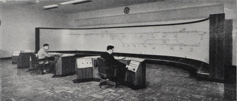
CONTROL and supervision of the power feed for any main-line electrification scheme poses its own peculiar problems, and with the advancement of the work on the Crewe to Stafford section of the London Midland Region it is of interest to examine the present control room at Crewe. Power feed to the Manchester-Crewe and Liverpool-Crewe sections is already supervised from the control centre and it is the first of four such centres which will eventually cover the entire electrification scheme to Euston.
Supervisory remote control
The Automatic Telephone & Electric Co. Ltd., working in close collaboration with the railway engineers, designed the supervisory remote control system for all sections in the Crewe control area, the unit providing the control engineer with continuous information relating to the entire power system together with facilities for operating the remote equipment, and indications that the required functions have been performed. If any circuit breaker trips out because of a fault he is made aware of this and can then take the necessary action to restore supplies. Visual and audible warning of alarm conditions, such as failure of signal, protection or battery charger supplies, is provided immediately on such a condition arising.
Enjoy more The Railway Magazine reading every month.
Click here to subscribe & save.
The mimic diagram
All this “information” is displayed in the control centre on a 51 ft. long by 6 ft. high mimic diagram, which is made up of 1-in. moulded plastic squares. Some of these are engraved with lines representing the overhead conductors and the feeder cables. Others are engraved with symbols representing circuit breakers and motorised switches and have a rotatable central portion and incorporate a lamp and a switch.
Operating the circuit breakers
Control is effected from the diagram itself through the control equipment in the apparatus rooms which signals over the transmission circuit to complementary equipment at each track sectioning cabin or feeder station. For example, to operate a circuit breaker the central portion of the relevant symbol is rotated manually to indicate the required condition, thus causing a coded pulse train to be transmitted to select the circuit breaker in readiness for the control signal. At the same time the signal lamp will glow, indicating that the condition shown by the symbol does not agree with the condition of the circuit breaker. From the appropriate track sectioning cabin the control equipment returns a “selection correct” signal, indicated visually on the diagram, and the required control signal is sent by operating the appropriate key. When the circuit breaker operates, the symbol lamp goes out and the diagram is again in agreement with system conditions.
Warning of changes
If any change of condition takes place without control the relevant symbol lamp flashes automatically and an alarm bell rings. By rotating the symbol to indicate the new condition the bell is silenced and the lamp goes out.
Telephone and signalling communications
Telephonic communication between the control centre and the track sectioning cabins and feeder stations is provided and a local telephone system provides contact between the diagram and the apparatus rooms. The signalling and speech circuits for the indication and control system are carried in line-side cables and some of the safeguards incorporated are main and main standby circuits with continuous monitoring, cable fault alarm and circuit change-over facilities, thus ensuring the reliability of operation which is so vital to the efficient control of the power network.
A two-position auto-manual telephone exchange provides internal telephone facilities within the control centre and is also connected to lines serving feeder stations, track sectioning cabins, repair depots, traffic control rooms and numerous track-side telephones used for maintenance and emergency purposes.
The original story appeared in The Railway Magazine and is accessible in the online archive, for Railway Magazine subscribers. Click HERE to subscribe, save and access!